
การประกอบเครื่อง
P2S
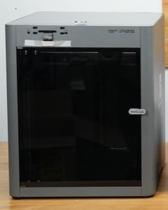
P2S, Tool Box, Spool Holder Assembly, Touchscreen, PTFE Tubes, Power cable.
|
|
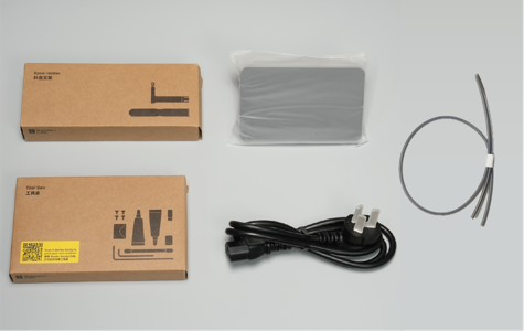
Note: The power cable is located in the top accessory box of the chamber.
Unboxing Stepsขั้นตอนการเอาเครื่องออกจากกล่อง
P2S Combo
Step 1 - Remove the Packageแกะกล่องแล้วหยิบคู่มือ
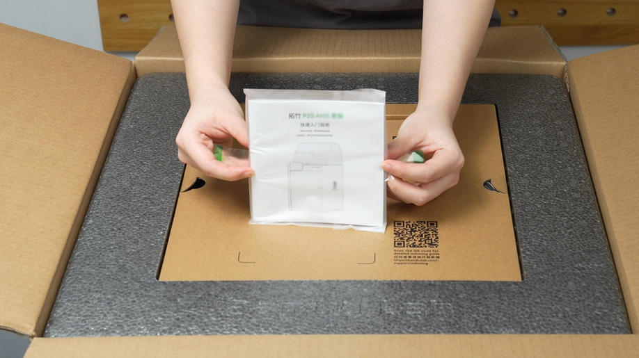
Open the outer box and take out the Tool Box andเมื่อเปิดกล่องมาแล้วจะเจอกับคู๋มือ Quick Start
Guide.
| ภาษาอังกฤษ แนะนำให้อ่าน หรือสแกน QR code เพื่อดูวิธีการประกอบ
|
|
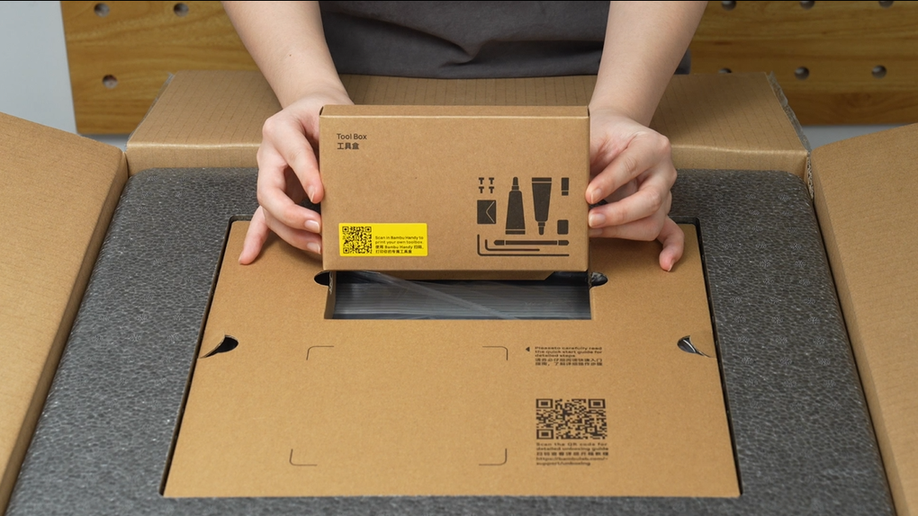
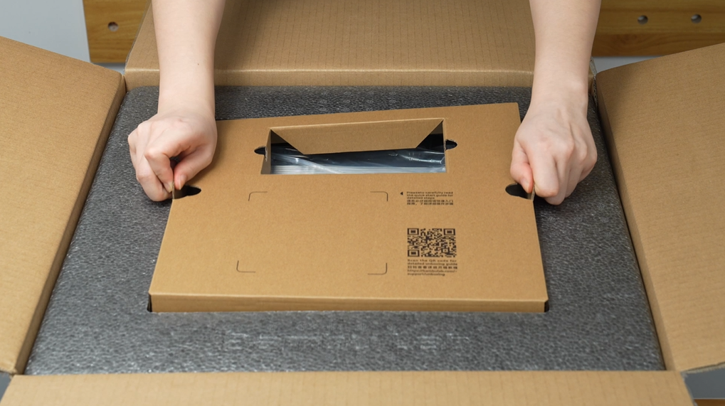
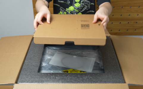
Remove the cardboard and top foam.
|
|
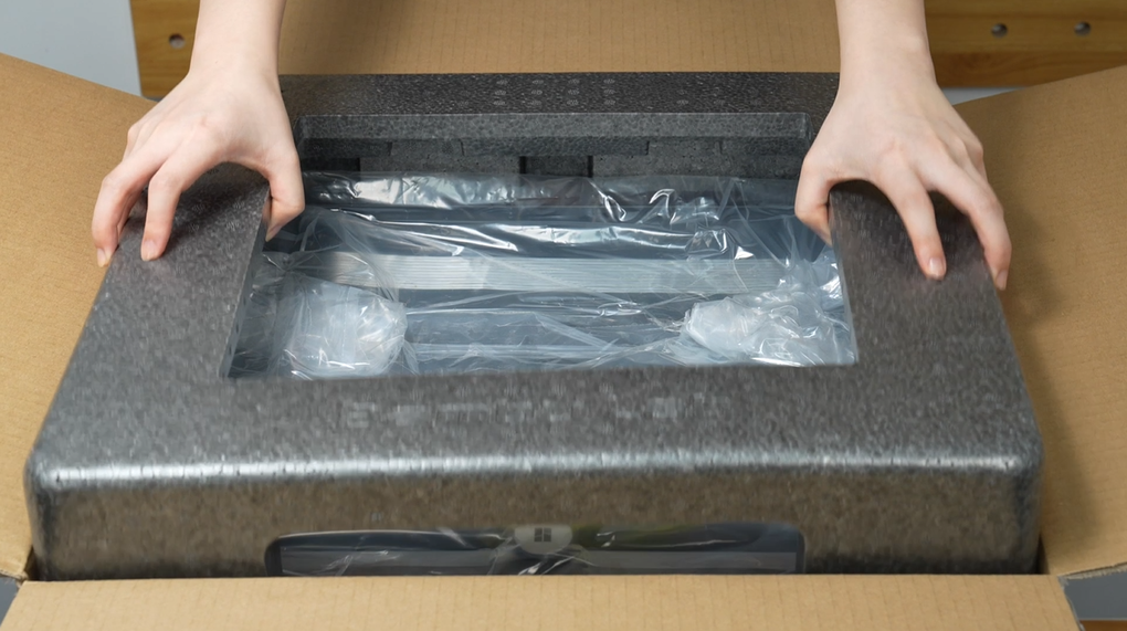
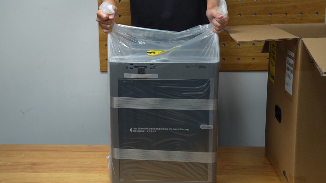
Lift out the printer, place it on a stable surface, and remove the moisture-proof bag.
|
|
Remove the tape from the bottom of the side panels.
|
|
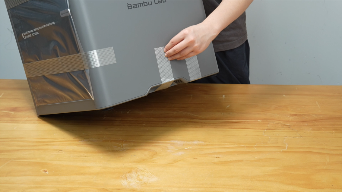
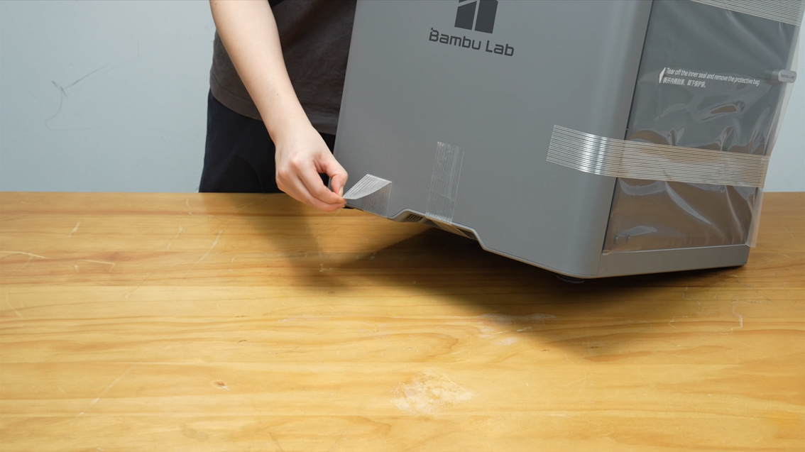
Failure to remove all tape from the bottom of the side panels may block cooling and affect printer performance.
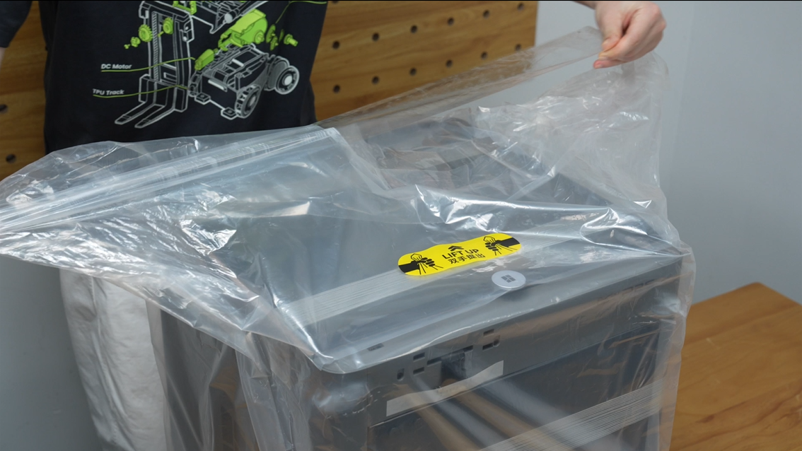
Peel off the top tape, remove the glass top cover, and take off the protective bag.
|
|
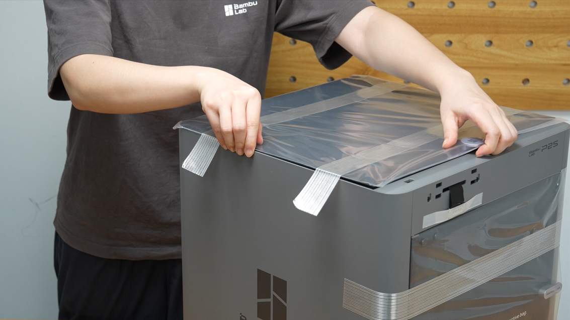
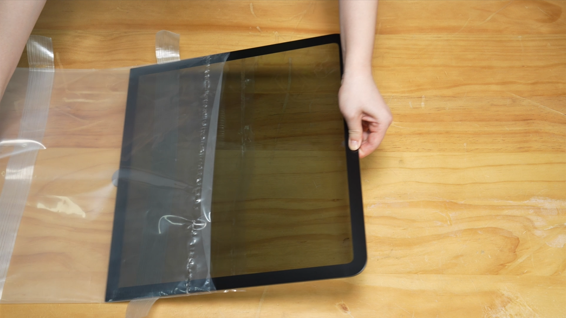
Peel off the tape on the front door and remove the protective bag.
|
|
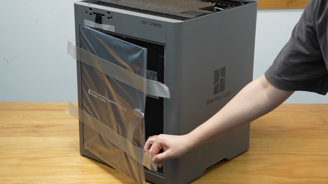
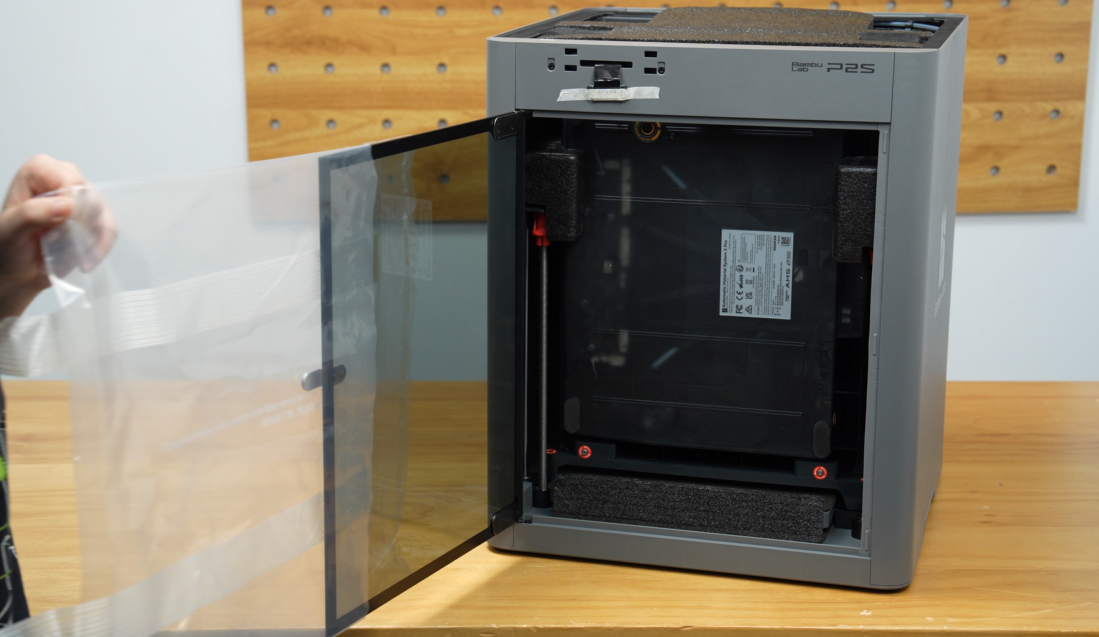
Step 2 - Take out Accessories and AMS 2 Pro
Take out the Accessory Box and remove all the top foam pieces.
|
|
|
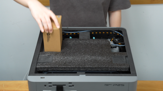
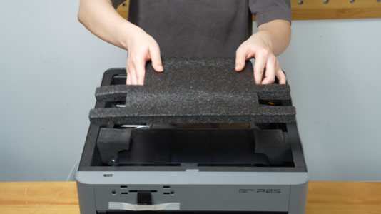
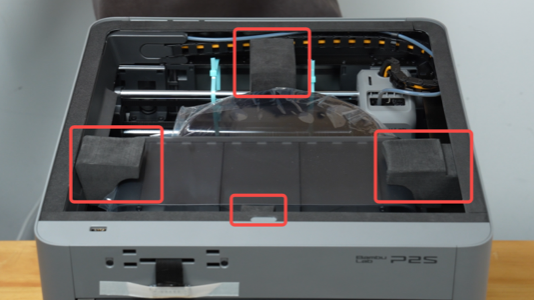
Use the H2.0 Allen key to remove the 2 screws marked in red.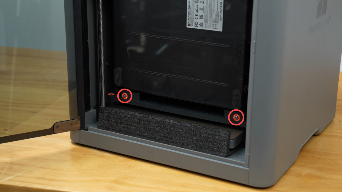
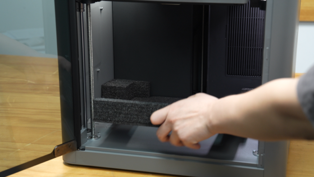
Keep the foam around the heatbed in place until calibration is complete.
Lift out the AMS 2 Pro and remove the foam protection around the AMS sides.
|
|
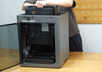
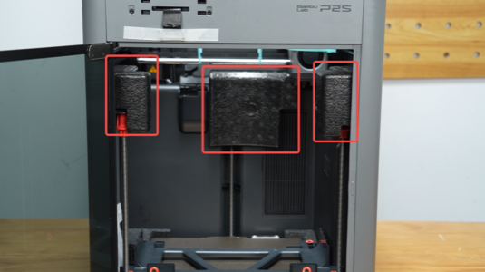
Packaging Update: The latest packaging no longer includes the left foam block inside the chamber. Simply remove the foam on the right and at the back.

Step 3 - Remove Transport Materials
Remove the 3 screws marked in red, then take out the transport fixture.
|
|
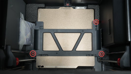
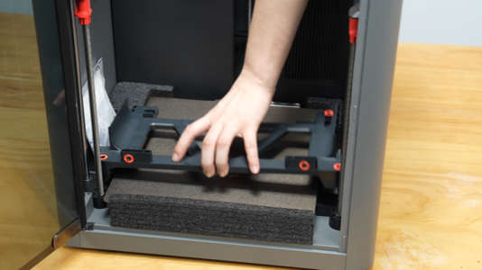
Remove the screw marked in red to unlock the heatbed.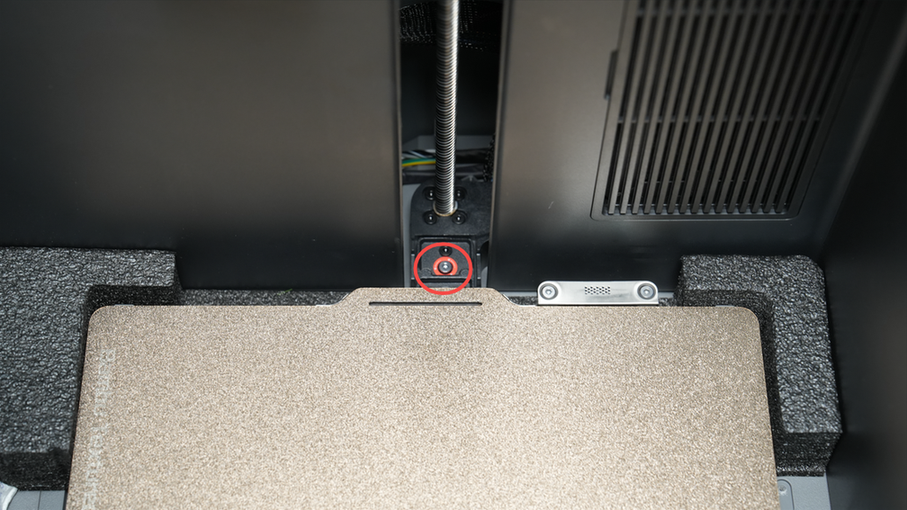
Note:When removing the heated bed fixing screws on the back of the printer, the screws may easily fall into the chassis. We recommend preparing a magnetic screwdriver, tweezers, or similar tools in advance to catch or retrieve the screws and prevent them from dropping into gaps inside the device.
Packaging Update: The latest packaging no longer includes the two foam blocks in front of the heated bed. If present, remove them at this step.
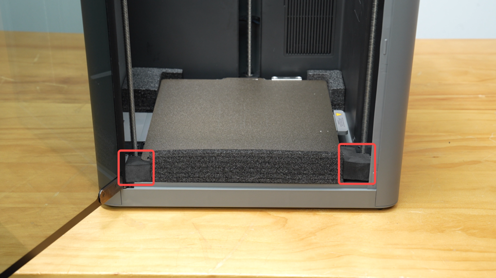
Remove the desiccant inside the printer.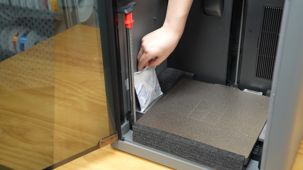
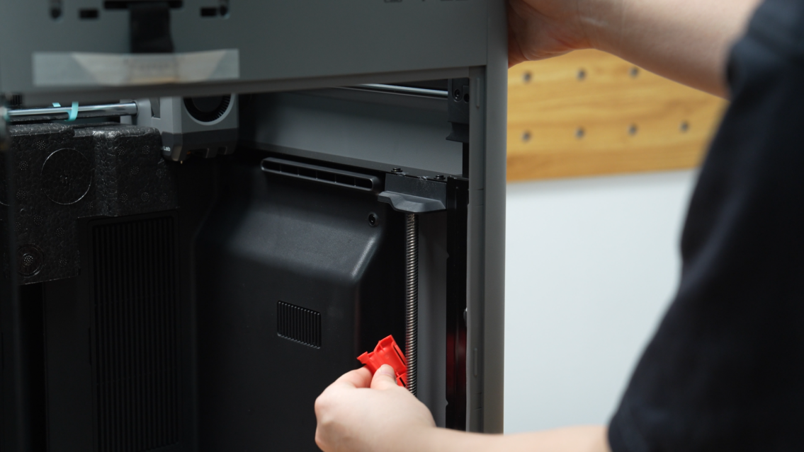
Pull down and remove the red plastic protectors from both lead screws.
|
|
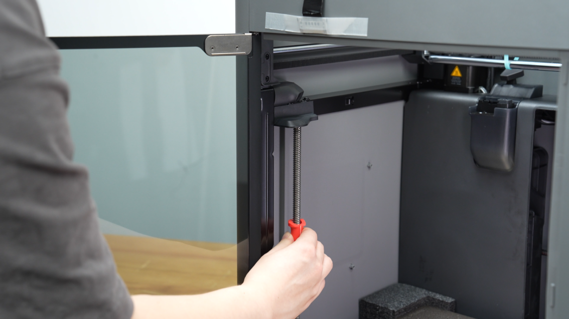
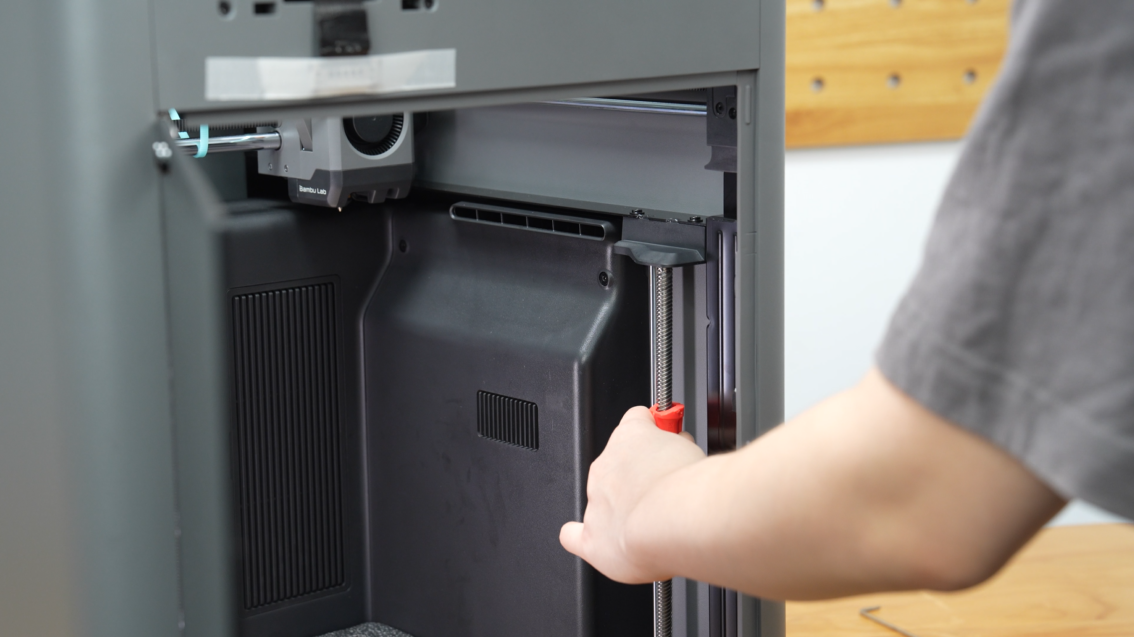
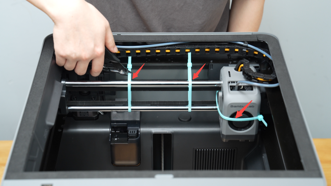
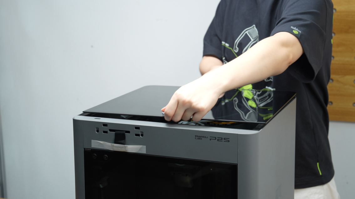
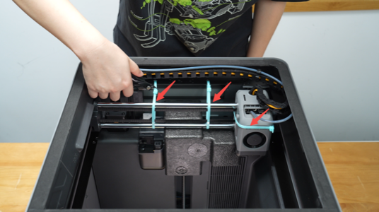
Cut and remove all zip ties, then place the glass top cover back onto the printer.
|
|
Step 4 - Install the Touchscreen
Remove the tape, then press the terminals on both sides of the cable and insert it into the screen port.
|
|
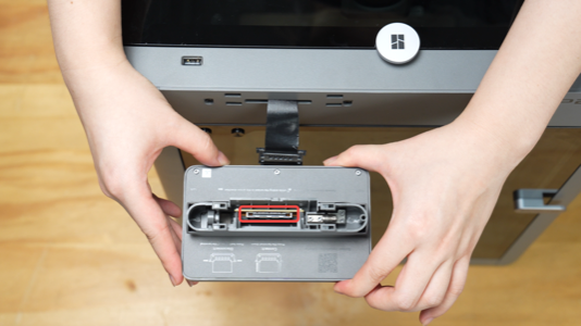
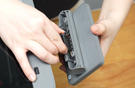
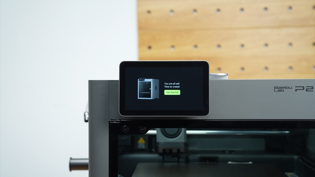
Push the flexible cable back into the printer slot. Then, insert the screen and slide it to the left to lock.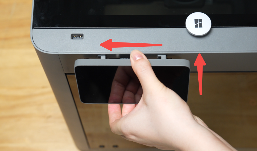
Step 5 - Install the AMS 2 Pro
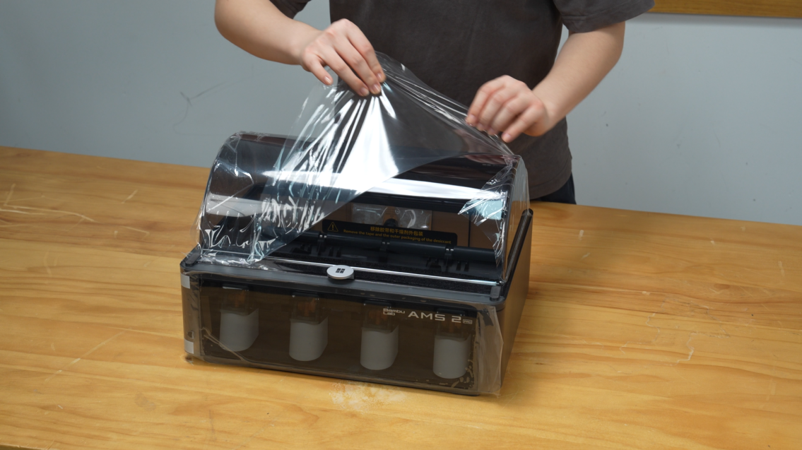
Remove the protective film and the inner foam from the AMS 2 Pro.
|
|
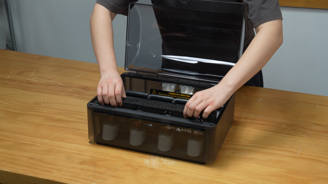
Take out the desiccant packs. Remove the packaging material and place them in the original place.
|
|
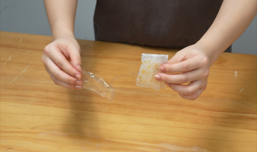
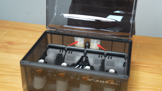
Place the AMS 2 Pro on top of the printer.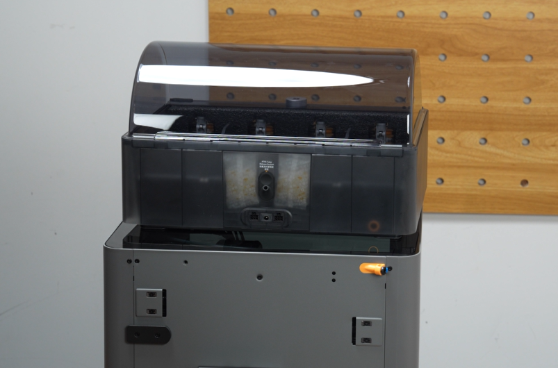
Remove the tape securing theท่อ PTFEtubeและandโฟมออกconnect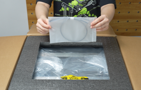
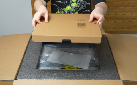
itto the PTFE tube coupler of the printer.
|
|
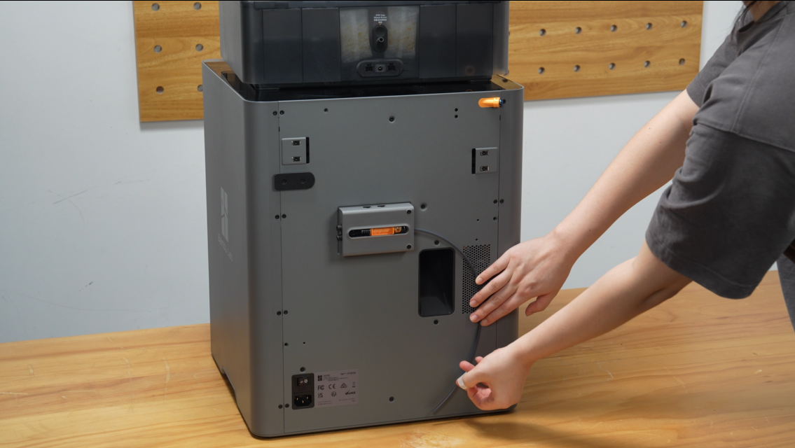
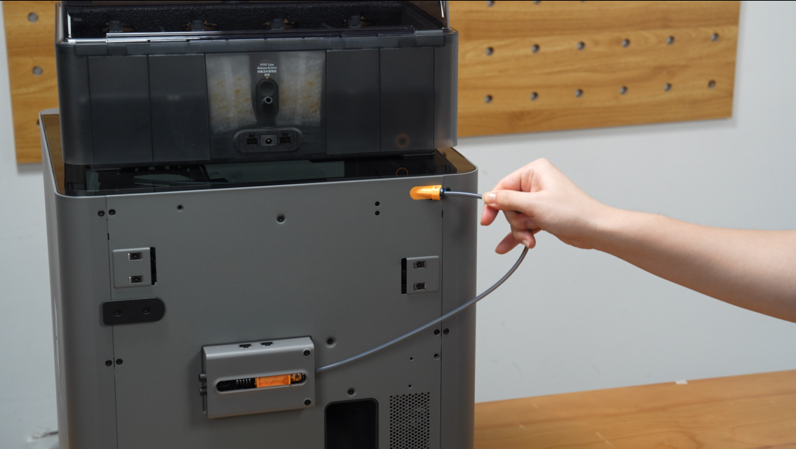
Insert the longest PTFE tube into the AMS 2 Pro's filament outlet and either PTFE tube coupler on the filament buffer.
|
|
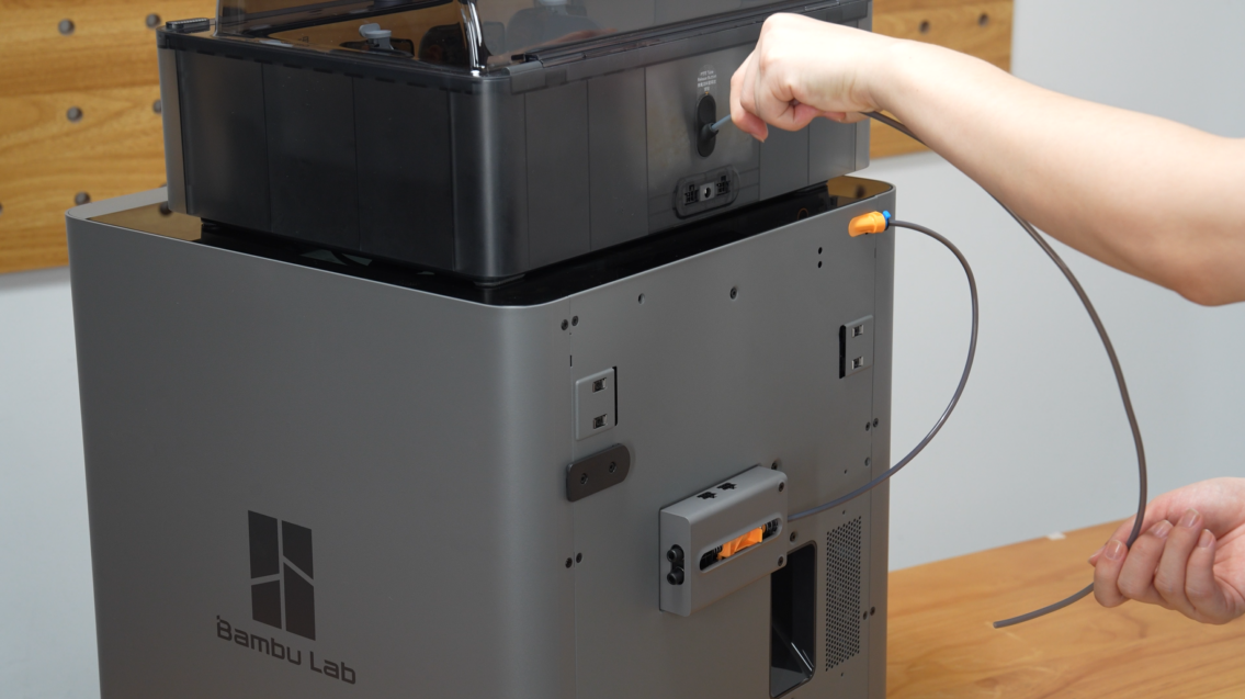
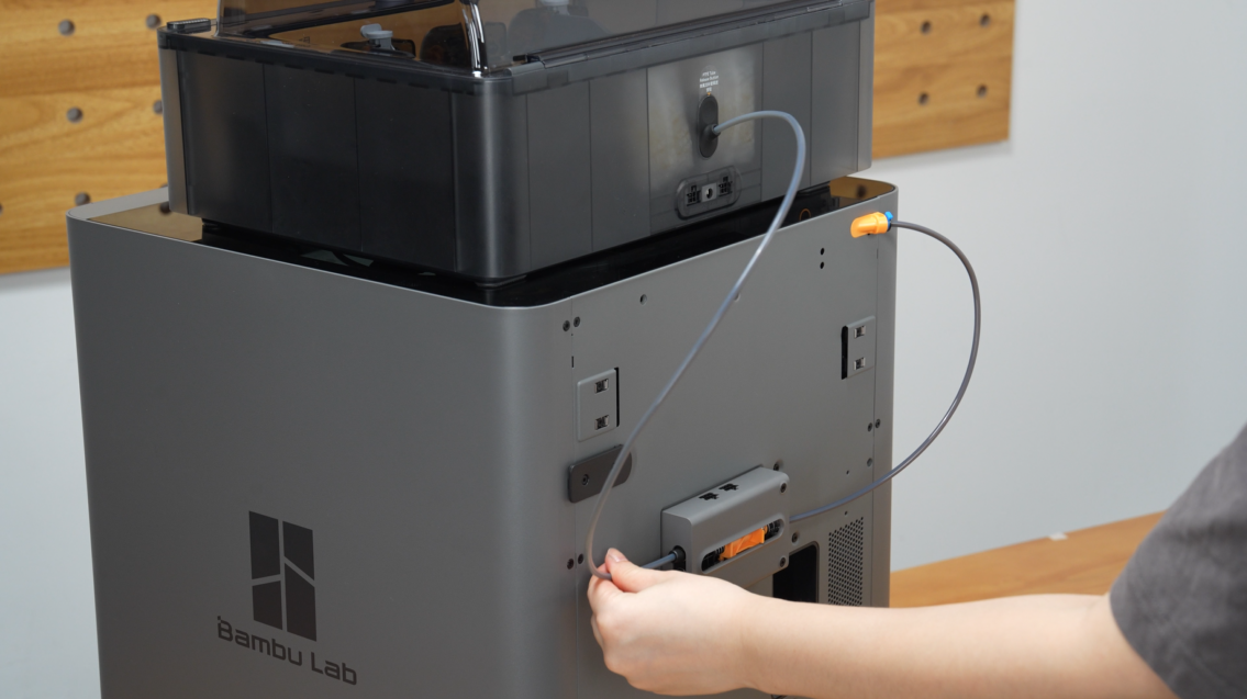
Insert the Bambu Bus Cable 6-pin into either 6-pin ports on the filament buffer and the AMS 2 Pro.
|
|
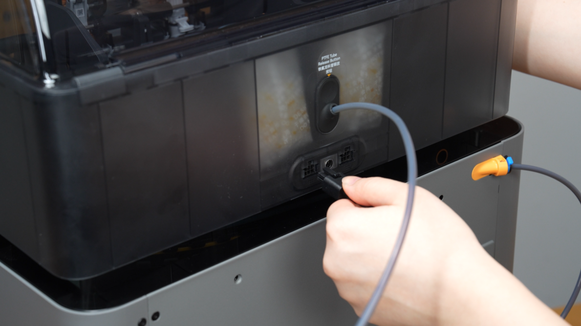
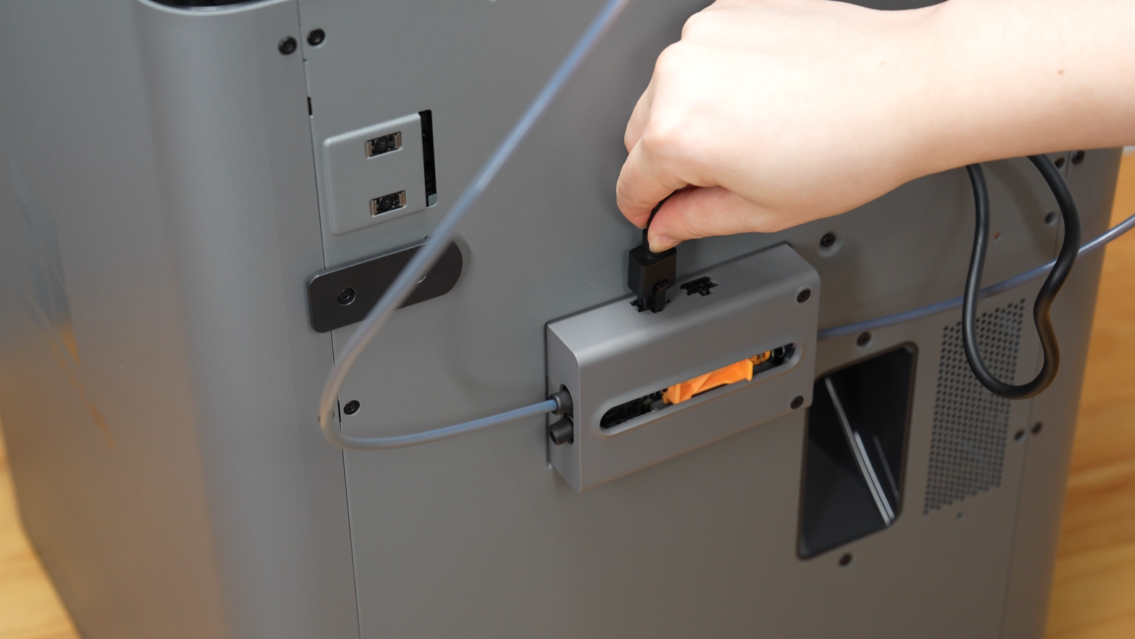
Step 6 - Install the Spool Holder Assembly
Slide the spool holder into the base plate until you hear a click.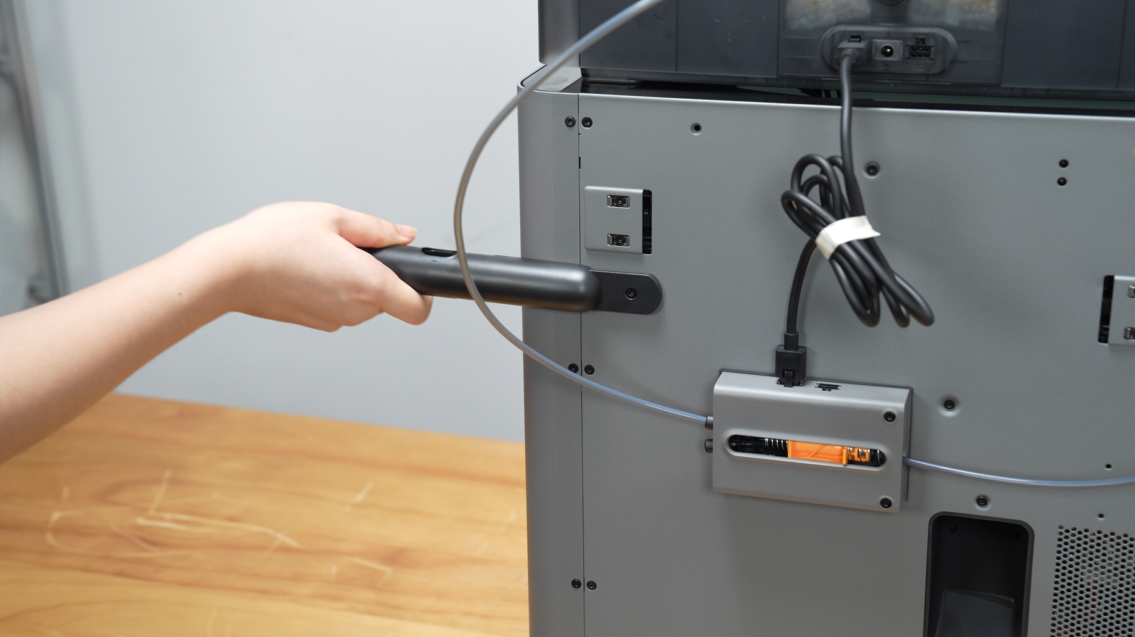
Insert the PTFE tube holder into the spool holder slot.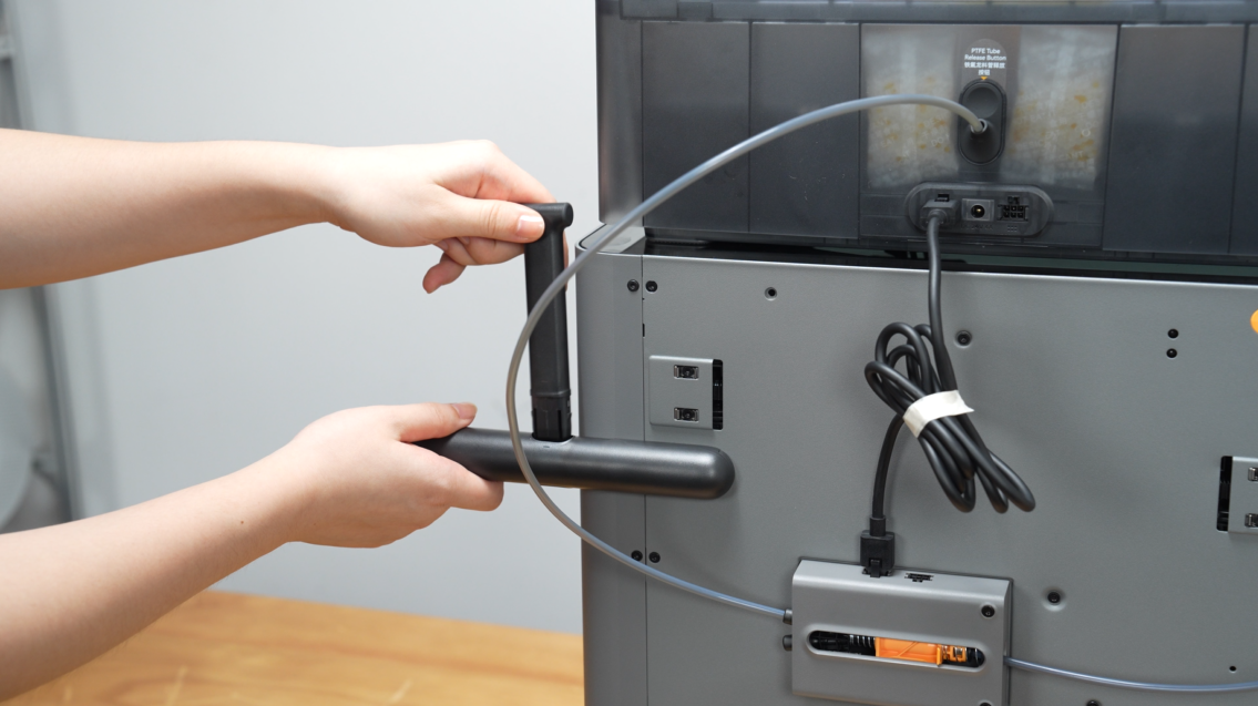
Insert the shorter PTFE tube into the tube couplers on the spool holder assembly and the filament buffer.
|
|
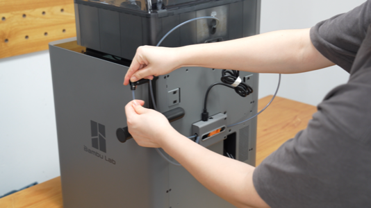
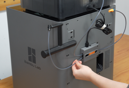
Reminder:To remove the PTFE tube connected to the filament buffer, press down the black pneumatic connector and gently pull the tube outward.When separating the spool holder, the first operation may be slightly laborious. It is recommended to shake the holder up and down first, then pull it out smoothly.


Step 7 - Power On and Calibrate
Plug in the power cable and turn on the printer.
|
|
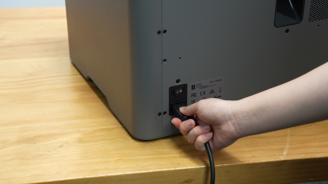
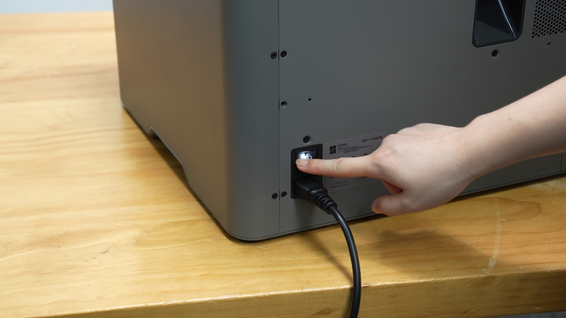
Follow the on-screen instructions to complete the initial calibration.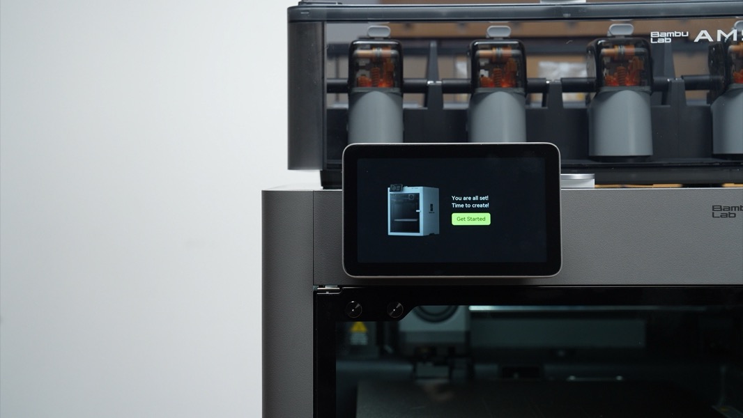
Before calibration, make sure that the build plate is properly placed on the heatbed.
After calibration, remove the foam under the heatbed.
|
|
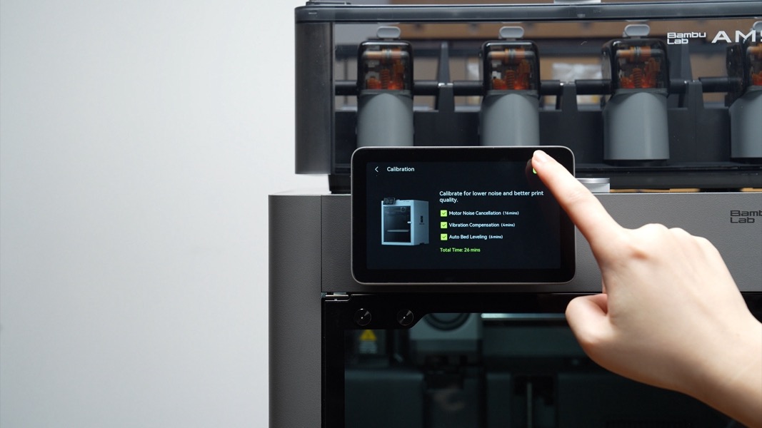
Everything is ready! Please refer to P2S First Print to start your first print.
P2S
Step 1 - Remove the Package
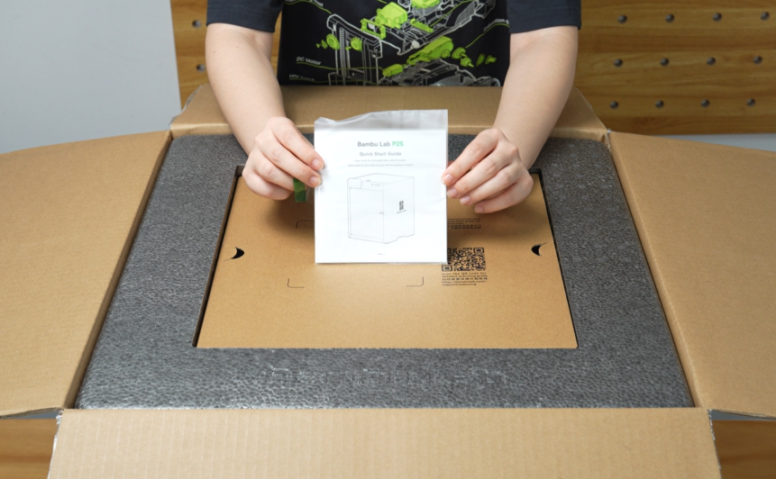
Open the outer box and read the Quick Start Guide.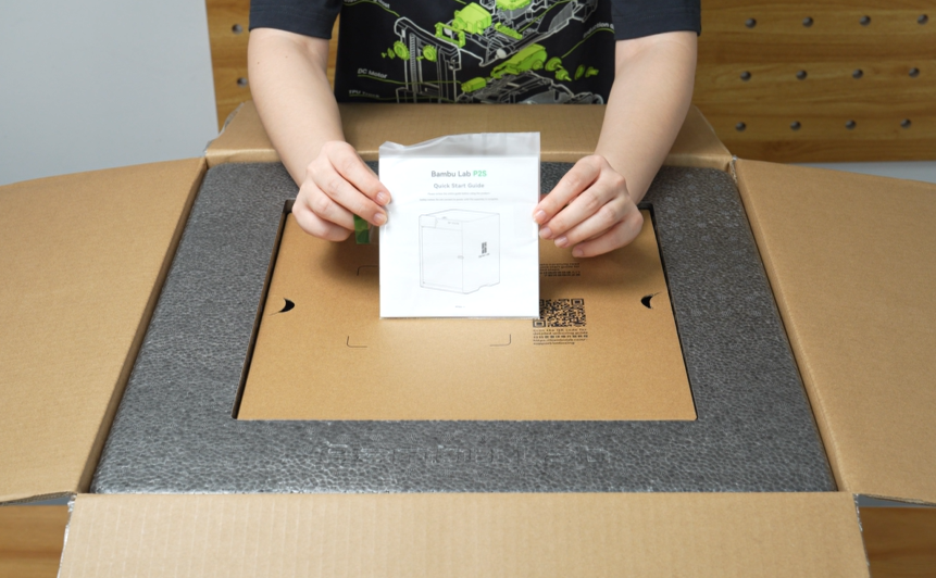
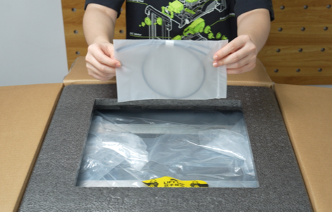
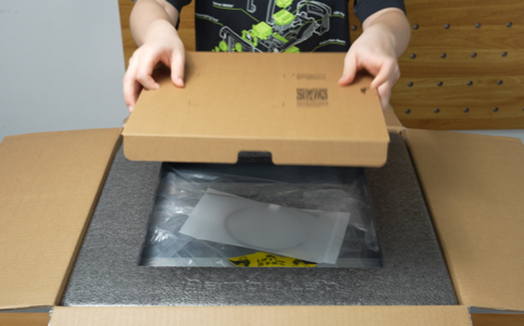
- Remove the cardboard, take out the PTFE tube, and then remove the top foam.
|
|
|
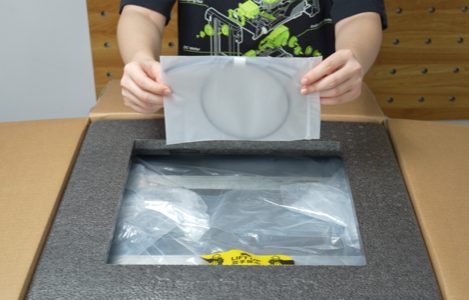
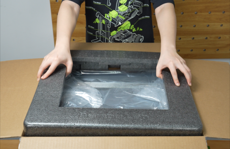
- Lift out the printer, place it on a stable surface, and remove the moisture-proof bag.
|
|
- Remove the tape from the bottom of the side panels.
|
|
Failure to remove all tape from the bottom of the side panels may block cooling and affect printer performance.
- Peel off the top tape, remove the glass top cover, and take off the protective bag.
|
|
- Peel off the tape on the front and remove the protective bag from the front door.
|
|
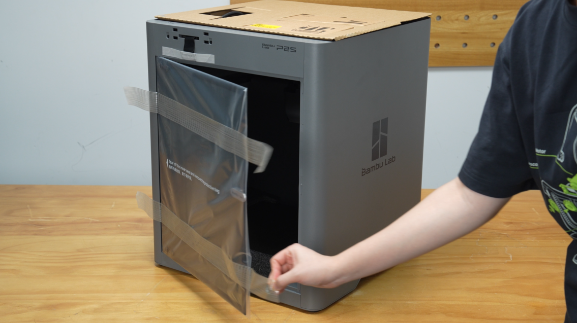
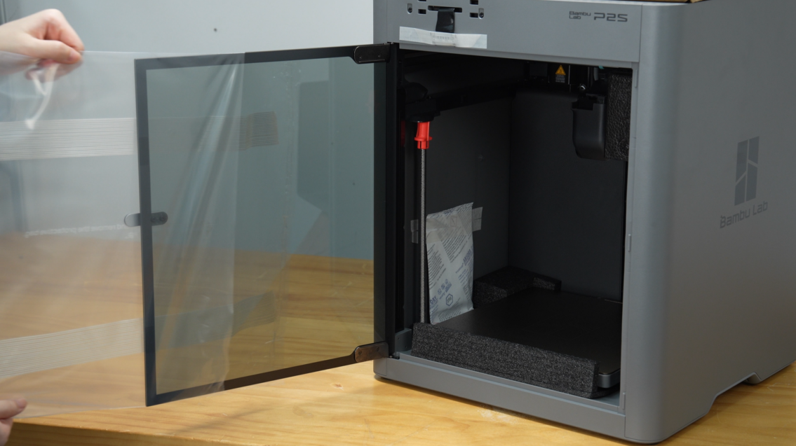
Step 2 - Take out Accessories
- Take out all accessories and remove the cardboard.
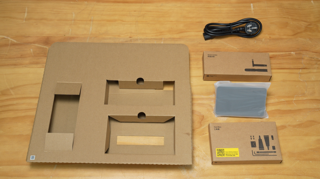
Step 3 - Remove Transport Materials
- Use the H2.0 Allen key to remove the 3 screws marked in red.
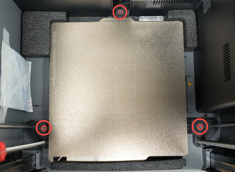
Note: When removing the heated bed fixing screws on the back of the printer, the screws may easily fall into the chassis. We recommend preparing a magnetic screwdriver, tweezers, or similar tools in advance to catch or retrieve the screws and prevent them from dropping into gaps inside the device.
Keep the foam around the heatbed in place until calibration is complete.
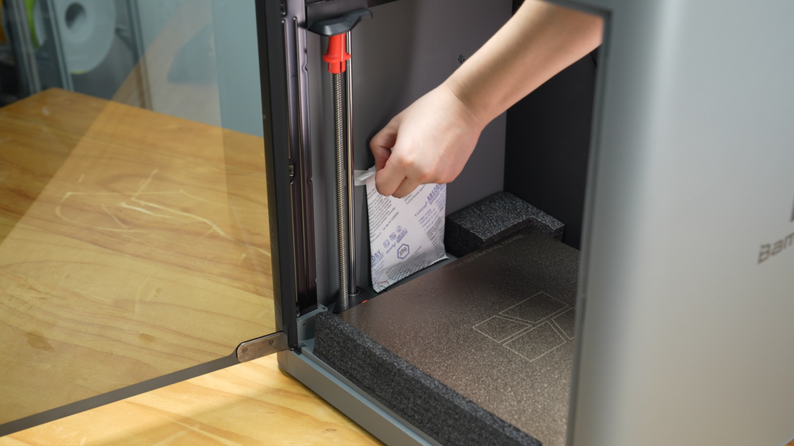
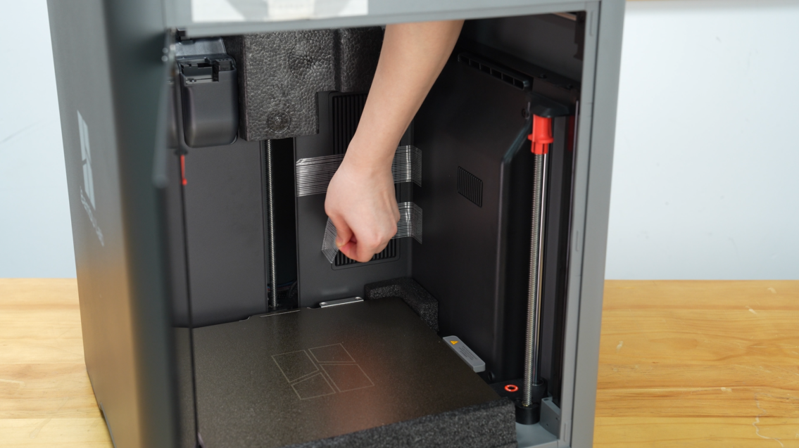
- Remove the desiccant and tape inside the printer.
|
|
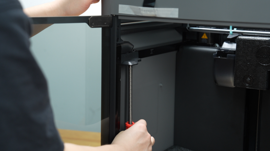
- Pull down and remove the red plastic protectors from both lead screws.
|
|
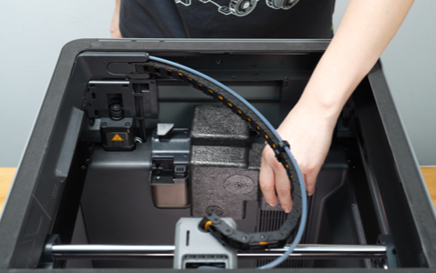
- Cut and remove all zip ties, move the toolhead forward, and remove the foam.
|
|
Step 4 - Install the Touchscreen
- Remove the tape, then press the terminals on both sides of the cable and insert it into the screen port.
|
|
- Push the flexible cable back into the printer slot. Then, insert the screen and slide it to the left to lock.
Step 5 - Install the Spool Holder Assembly
- Slide the spool holder into the base plate until you hear a click.
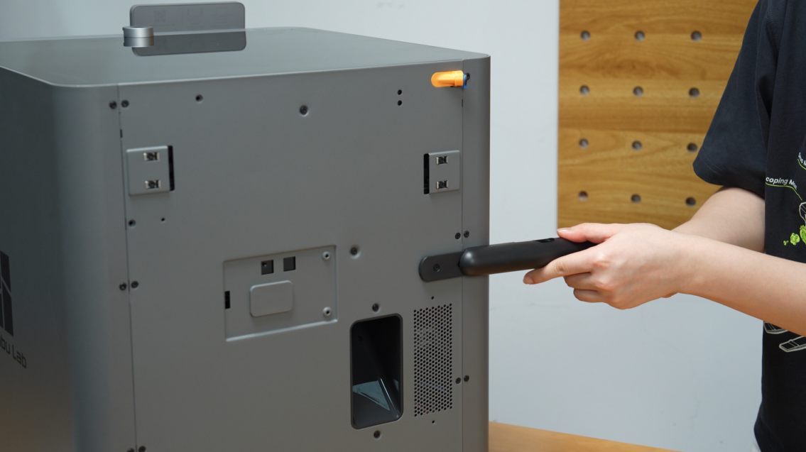
- Insert the PTFE tube holder into the spool holder slot.
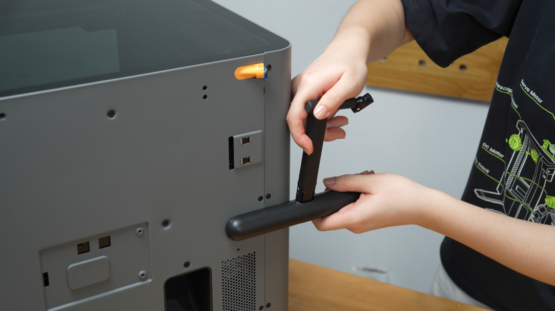
- Insert the shorter PTFE tube into the tube couplers on the spool holder assembly and the printer.
|
|
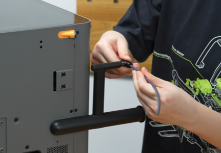
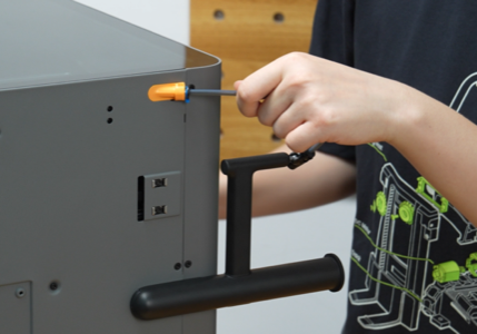
Reminder: When separating the spool holder, the first operation may be slightly laborious. It is recommended to shake the holder up and down first, then pull it out smoothly.
Step 6 - Power On and Calibrate
- Plug in the power cable and turn on the printer.
|
|
- Follow the on-screen instructions to complete the initial calibration.
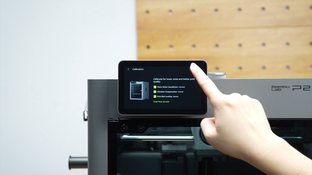
Before calibration, make sure that the build plate is properly placed on the heatbed.
- After calibration, remove the foam under the heatbed.
|
|
Step 7 - Place a box or container to catch filament purges which fall from the chute
The small box which filament is shipped in is a great solution to this until a better alternative can be set up. Be sure to place the container below the rectangular purge chute opening at the back of the printer (example on a P1S pictured below).

A more permanent solution may be printed later by searching for an P2S purge container on MakerWorld.
Everything is ready! Please refer to P2S First Print to start your first print.